Freestanding Hydronic Convectors
SOODIA Freestanding Hydronic Convectors provide above-floor heating for interiors where the appliance remains visible and pipe connections must be coordinated with the room layout. They connect to a heating water system; freestanding describes the mounting format, not a portable electric heater. Hotel interiors, sales halls and other commercial spaces are illustrated applications. The enclosure becomes part of the interior detailing, making connection access and the appearance of the pipework important decisions alongside the required heat output.
Series 01 offers exposed connection access, including left- or right-side arrangements. Series 02 conceals the pipework and valve area within the casing for a more integrated appearance. Compare these details before choosing the enclosure dimensions. A freestanding unit sits above the finished floor, unlike a trench convector whose body is recessed below it. It also differs from the wall-mounted family and from perimeter equipment incorporated into a window-sill enclosure. Standard models and custom configurations can be considered against the available space, but a preferred visual arrangement still needs to be checked with the heating water conditions and the installation drawing for the selected series.
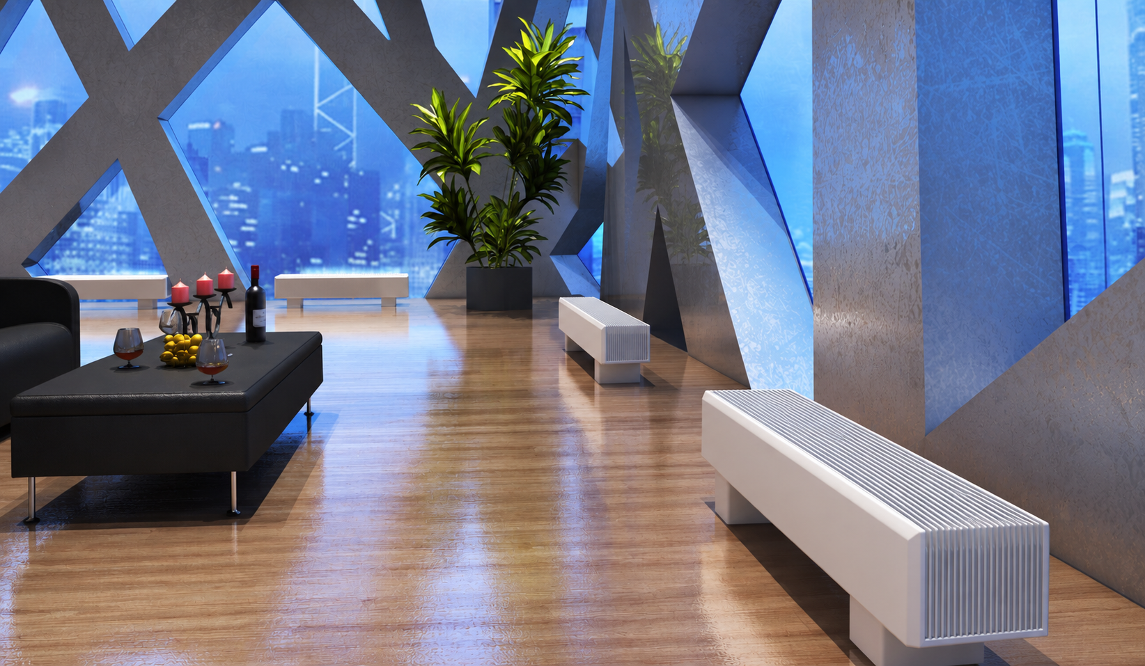
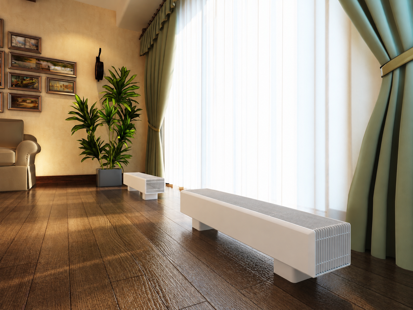
Explore Product Versions
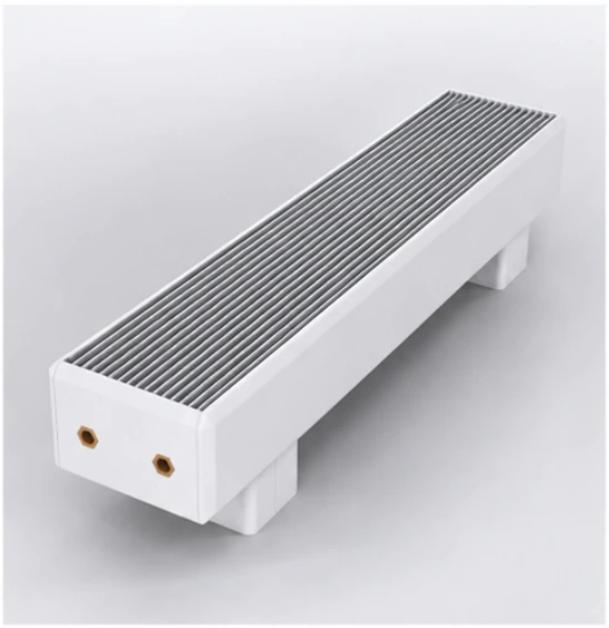
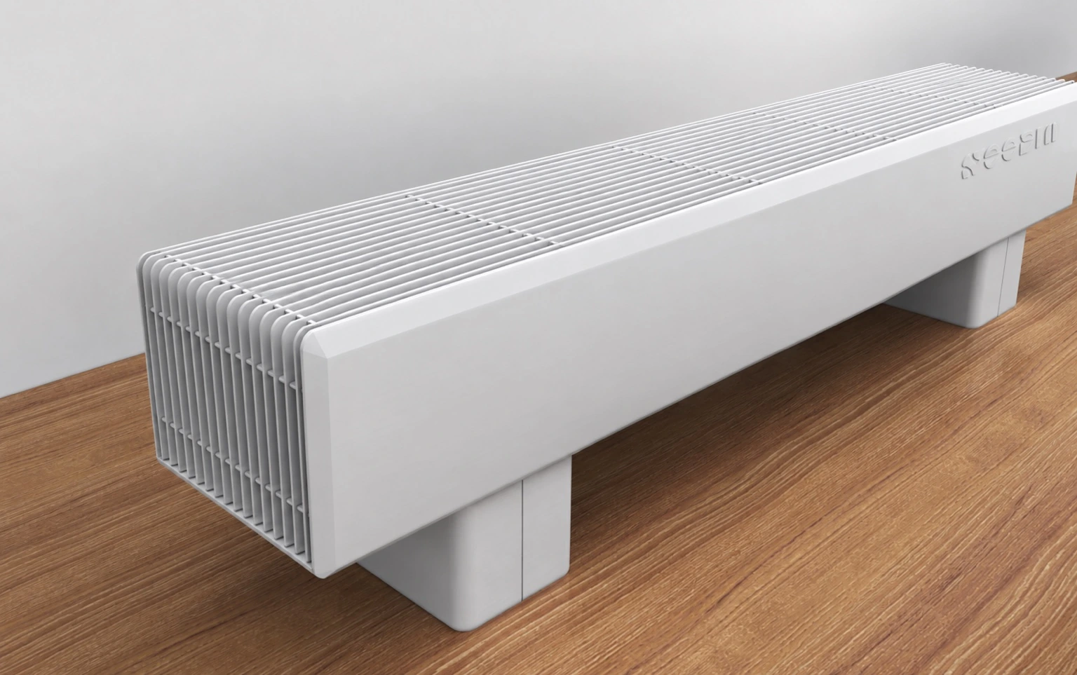
How it works
The copper-tube exchanger receives heated water from the building's heating circuit. Air moving through the enclosure picks up heat and returns to the room; the unit therefore needs an unobstructed path around its air openings. Natural convection relies on warmed air rising, whereas forced convection uses a fan to drive airflow. The published Series 01 and Series 02 descriptions focus on their connection arrangements and do not establish a fan-assisted option, so do not assume one from a different SOODIA range.
The series PDFs publish output tables at different water and room temperatures. Read across the correct temperature column for the proposed system, then compare the corresponding model and dimensions. Concealed valves are an installation and appearance choice, not evidence of a particular output increase. Select the thermal duty and the connection arrangement together so that neither the room design nor the heating calculation is treated as an afterthought.
Selection table
Examples from the Series 01 and Series 02 PDFs, page 2 of each. Outputs use the 80/60/18°C column. Height refers to the body shown in the diagram, excluding floor clearance/supports. DN15/DN20 options are stated on the Series 01 page; confirm the option for the exact model rather than applying it to Series 02.
| Model | Length (mm) | Body height (mm) | Heat output (W) |
|---|---|---|---|
| STDDMYC-110-130/800 | 800 | 110 | 423 |
| STDDMYD-300-130/800 | 800 | 300 | 549 |
Source PDF — Series 01 · Source PDF — Series 02
Installation
Place the proposed unit on the room plan and show its relationship to glazing, furniture, circulation routes and the finished floor. A floor-standing unit still requires permanent heating-water connections and a coordinated mounting detail. Check the selected drawing for the body dimensions, supports and pipe entry locations; body height should not be confused with the total installed height. Existing installation illustrations show the overall concept but do not replace a dimensioned drawing for the chosen model.
For Series 01, decide which side offers practical connection access and whether side or bottom pipe entry suits the building services. For Series 02, establish how the concealed valve area will remain accessible once nearby finishes and furniture are in place. Review these access needs before the pipework is fixed. Keep the air path around the enclosure clear, and coordinate any floor penetrations with the construction team. Where custom dimensions are requested, submit the proposed length, body height and depth together with the pipe route; changing the casing size alone is not a complete installation brief.
Materials and finishes
Both series use a copper-tube heat exchanger within a visible enclosure. Series 01 leaves connection details exposed; Series 02 encloses the pipework and valve area and is described with smooth, rounded edges. These differences should be reflected in the finish review, especially where the appliance is close to furniture or publicly accessible circulation space. The current family information does not specify a universal casing material, fin material or colour chart for every model. Include a finish reference and any custom enclosure requirements in the enquiry, and have the selected construction confirmed. Do not infer material grades or a safety certification from the appearance of the product photographs.
Project documents
Provide the room layout, required heating output, design supply and return water temperatures, room temperature and quantity. Indicate Series 01 or Series 02 and draw the preferred connection position, including the finished floor level and space for access. Download the selected series PDF for its model schedule and dimensional drawings; the two series should not be selected from a shared assumed output. State whether the dimensions describe the body or the installed assembly. A marked-up drawing is especially useful when reviewing a concealed connection or a custom enclosure beside glazing.
BUYER GUIDE
Also specified in project documents as a freestanding convector, floor-standing convector or free-standing radiator.
Selection questions
What is the difference between Freestanding Hydronic Convector-01 and -02?
Freestanding Hydronic Convector-01 provides exposed connection access. Freestanding Hydronic Convector-02 conceals pipework and valves within the connection area. Compare the product drawings with the planned pipe route and installation space.
Does freestanding mean this is a portable plug-in heater?
The freestanding hydronic convectors shown in this range are hydronic units connected to a heating water system. Freestanding describes the floor-standing installation format; it does not mean the product is a portable plug-in electric heater.
What should I specify before requesting a quotation?
Include the preferred connection arrangement, unit dimensions, heating water conditions, required output if known and quantity. Use the technical PDF for the selected version to review its dimensions and connections.
Technical reference sources
BSI provides the scope of EN 442-2 for radiator and convector output testing. Check the selected model’s test conditions and supporting documents when comparing performance.
These links are independent background references, not evidence that SOODIA or a listed model holds the referenced certification. Request model-specific evidence for your project.